Industrial Vision Systems: A Practitioner's Guide
Master industrial vision systems with this practitioner's guide covering components, selection criteria, deployment pitfalls, and ROI for manufacturing AI.
Written by AI for Manufacturing
Industrial vision systems use cameras, optics, lighting, processing hardware, and software to capture and interpret visual data for automated decisions on the factory floor. The industrial machine vision market was estimated at USD 16.11 billion in 2025 and is projected to reach USD 33.40 billion by 2034, with an implied 8.44% CAGR over that period, according to Fortune Business Insights.
The popular advice is to start with the AI model. That's usually backwards. Production failures more often begin with insufficient examples of rare defects, false calls that destroy operator confidence, unstable lighting, or an inspection result that never reaches the PLC and MES in a usable form. A vision line succeeds when the entire sensing and decision path is engineered for the factory, not when a model performs well on a carefully selected test set.
Table of Contents
- What Industrial Vision Systems Actually Do
- The Core Components of an Industrial Vision Stack
- Architecture Choices and How They Map to the Factory Floor
- Evaluating Vision Systems by Performance and Fit
- Deploying and Validating a Vision Line Without Surprises
- ROI, Use Cases, and What Real Manufacturing Pilots Actually Do
- Lessons From the Field and Where to Go Next
What Industrial Vision Systems Actually Do
Industrial vision systems do more than detect defects. They inspect presence and absence, measure dimensions, read codes, verify assembly, guide robots, classify parts, and trigger actions such as reject, divert, stop, or rework. A typical system combines an industrial camera, lens, light source, processing hardware, and image-analysis software configured around a specific task, as outlined in this industrial machine vision overview.
That distinction matters for anyone pursuing AI in manufacturing. A defect classifier is only one component in a closed-loop production system. The camera must see the relevant feature, the image must arrive within the cycle budget, the algorithm must return a decision with an acceptable false-call rate, and the control layer must execute the decision consistently.
Why pilots stall before production
The most persistent deployment barriers are operational. A machine vision survey identified lack of critical data at 62%, false calls in inspection at 56%, difficulty handling complex surfaces at 50%, and integration with existing infrastructure at 41% among the leading obstacles. Those findings are reported in the Machine Vision Survey.
Teams often collect thousands of normal images and very few examples of the defect they need to find. That creates a training set that looks complete but gives the model little evidence about borderline conditions, surface variation, tooling wear, or changes between shifts. The result can be a model that scores well in development and causes production staff to bypass it because it rejects too many good parts.
Practical rule: Treat false rejects as a production-loss problem, not merely a model-quality problem.
Systems that run reliably for years tend to share a less glamorous design. They use constrained inspection points, controlled illumination, repeatable part presentation, clear pass-fail definitions, and a curated image set that includes approved, marginal, and rejected parts. Deep learning can handle variation that defeats rigid rules, but it can't recover information that the optics never captured.
What this means for manufacturing AI
Industrial vision is often an accessible entry point for manufacturing AI because the decision is tied to a physical object and an observable process event. It also exposes the discipline required for broader AI initiatives. Data provenance, edge latency, PLC handshakes, operator workflows, model versioning, and maintenance all become visible at the line.
The technology has a long commercial history. Industrial Vision Systems was founded in 2000 and marked its 20th anniversary in 2020; a company profile stated that it had supplied thousands of vision systems worldwide by that point, illustrating the category's industrial scale before the current deep-learning wave. The industrial machine vision market background from GM Insights provides that historical context.
The Core Components of an Industrial Vision Stack
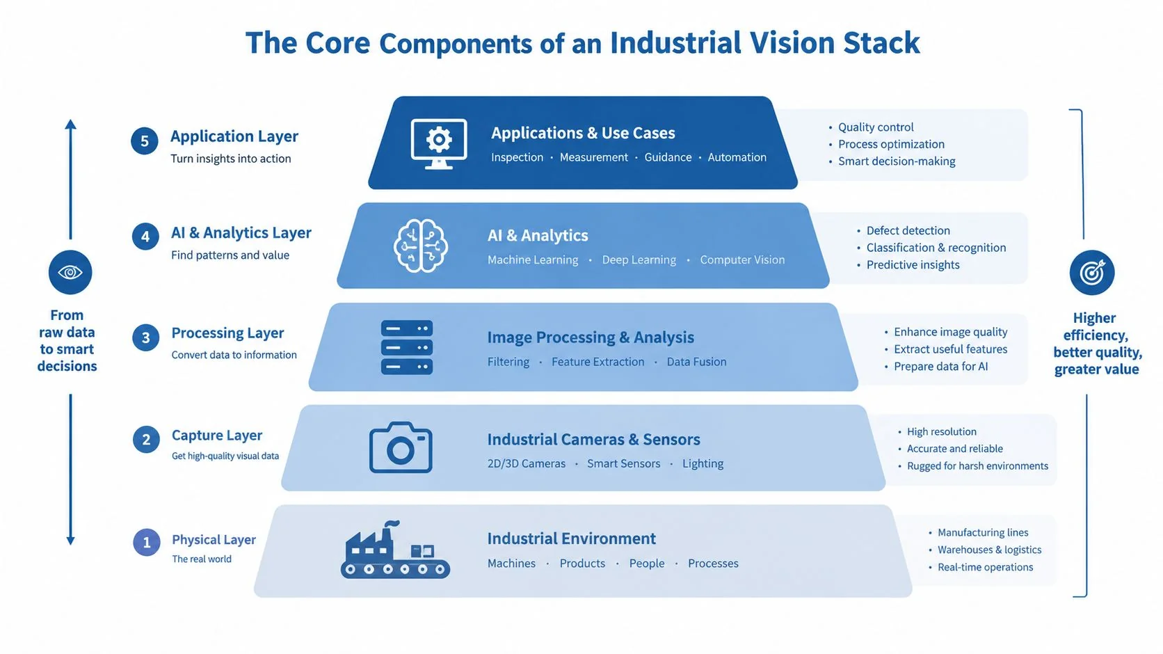
Consider a stamped metal bracket moving through a tabletop inspection cell. The system must confirm the bracket's hole is present and correctly positioned, verify the edge profile, and identify surface damage. Each layer contributes to that result, and a weak choice at one layer can make the rest of the stack irrelevant.
Start with the image
Camera, the inspector's eyes. A 2D area-scan camera captures the bracket in a discrete frame, which suits a fixed station or indexed conveyor. A line-scan camera builds the image line by line as the part moves, making it better for continuous webs or long surfaces. Sensor size, shutter type, exposure, frame rate, and available resolution determine whether motion is frozen and whether the smallest feature contains enough usable pixels.
Optics, the prescription glasses. The lens sets field of view, working distance, magnification, and distortion. A wide field of view may capture the entire bracket but leave the hole represented by too few pixels. A narrow field of view can resolve the hole and edge accurately but may require multiple cameras or tighter mechanical tolerances.
Lighting, the controlled inspection booth. The light source makes the feature visible. Backlighting silhouettes the bracket and is effective for hole and edge measurement. Dark-field lighting emphasizes scratches and raised features. Dome lighting reduces harsh reflections on curved or semi-gloss surfaces, while coaxial lighting can reveal markings on flatter reflective areas.
Processing, the foreman's brain. A smart camera keeps acquisition and inference together at the station. An industrial PC supports multiple cameras and heavier algorithms. FPGA processing can deliver deterministic timing, while an edge GPU supports deep-learning inference close to the actuator. The right choice depends on image count, model complexity, line speed, serviceability, and plant standards.
Software and algorithms, the rulebook plus pattern recognition. Classical tools handle geometry, thresholding, edge detection, barcode reading, and measurement when the part presentation is controlled. Deep learning is more useful when defects vary in shape, texture, or location. Many reliable systems use both, for example, a learned defect classifier followed by a deterministic dimensional check.
For a broader connection between visual inspection and equipment health, this guide to predictive maintenance ML is useful because it shows how image data can sit alongside vibration, temperature, and other maintenance signals. Integration teams also benefit from this computer vision factory-floor guide when mapping the stack to production workflows.
Design the layers together
The camera, lens, lighting, and processing unit aren't independent shopping-list items. A faster camera is wasted if the light can't freeze motion. A powerful GPU won't fix glare. A high-resolution sensor can increase data volume and processing latency without improving the decision if the lens and field of view are poorly matched.
A practical planning constraint is that the smallest defect should span roughly 3 to 5 pixels on the sensor to be distinguished reliably from noise and surface texture. Pixel size, working distance, and field of view therefore belong in the first engineering review, not in a late-stage troubleshooting meeting.
Industrial connectivity matters too. GigE Vision uses Ethernet and Internet Protocol standards to control vision devices and transmit vision data, and the standard is managed by the Association for Advancing Automation, as described by Cisco. That interoperability can simplify multi-vendor integration, but it doesn't remove the need to define timing, triggers, data ownership, and failure behavior.
Architecture Choices and How They Map to the Factory Floor
Architecture should follow the plant's operating profile, not a vendor's preferred product category. A single-station inspection with one camera has different needs from a multi-camera line that must coordinate several decisions with a robot, PLC, and MES.
| Architecture | Best-Fit Deployment Profile | Typical Constraints | Integration Cost Signal |
|---|---|---|---|
| Standalone smart camera | One inspection point, moderate line speed, simple PLC footprint, local controls | Limited compute and flexibility, constrained camera count, vendor-specific tooling | Low initial cabinet and wiring burden, but replacement and expansion can become costly |
| PC-based system with frame grabber or GigE | Multiple inspection points, higher image volume, complex algorithms, established industrial PC standards | Requires cabinet space, thermal management, software maintenance, and stronger change control | Moderate to high, depending on camera count, I/O, and PLC or MES interfaces |
| Embedded edge AI device | Latency-sensitive robot guidance, decentralized decisions, distributed cells, local OT governance | Hardware lifecycle, model deployment discipline, limited memory or accelerator options | Moderate, with added cybersecurity and device-management work |
| Cloud-assisted architecture | Central training, cross-site governance, large model-development workflows, strong IT support | Bandwidth, latency, data-transfer controls, plant connectivity, cloud dependency | Potentially high once network, security, data retention, and support requirements are included |
The practical trade-off
A smart camera is attractive when the inspection is narrow and the controls team wants a compact installation. It becomes limiting when the line adds cameras, more complex models, or a requirement to correlate images across stations.
A PC-based system is often the most flexible choice for multi-camera lines and heavier algorithms. That flexibility comes with a larger software and infrastructure footprint. Teams need to plan image storage, remote support, industrial networking, cabinet space, and recovery behavior after a reboot.
Embedded edge AI is compelling when a robot or actuator needs a decision close to the process. It reduces dependence on a round trip to a central server, but distributed devices create a fleet-management problem. Model versions, security patches, configuration backups, and health monitoring must be handled consistently.
Cloud assistance can support centralized training and governance, particularly when multiple plants share data. It's a poor fit for a hard real-time reject decision if network latency or connectivity is uncertain. Before selecting a cloud-connected design, define what happens when the link is unavailable and whether the line can continue safely.
For PLC and industrial interoperability, the OPC UA communication protocol guide gives useful context. The cheapest hardware option rarely remains the cheapest system after integration labor, validation, cybersecurity review, training, and lifecycle support are counted.
Evaluating Vision Systems by Performance and Fit
A shelf-bound vision system usually passed a demonstration. A production-ready system survives variation. The evaluation must therefore connect optical performance, algorithm quality, controls behavior, and environmental durability.
The first engineering check is defect geometry. The smallest defect should cover approximately 3 to 5 sensor pixels for reliable distinction from noise and texture, according to industrial vision guidance published through PMC. The same source describes online vision accuracy of roughly 0.2 to 0.5 millimeters over a 2-meter range, stereo vision reaching about 50 micrometers under controlled conditions, and time-of-flight systems at around 10 millimeters. These aren't interchangeable specifications. They describe different sensing methods and operating conditions.
Evaluate the line, not the laboratory
Accuracy matters, but repeatability often matters more to operations. A model that detects every defect in a static test can still fail when parts arrive with changed orientation, oil residue, vibration, ambient light, or tooling wear. Measure the system at the actual takt, with actual operators and normal process variation.
Track these line-side metrics:
- Defect escapes: Parts that should have been rejected but passed.
- False rejects: Good parts removed from production, including the labor and investigation queue they create.
- Decision latency: Time from trigger to result, including image acquisition, inference, PLC communication, and actuator response.
- Repeatability: Whether the same part produces the same result after cycling, shift changes, or controlled restarts.
- Availability: Whether the system recovers predictably from camera, network, or processing faults.
- Environmental tolerance: Performance under vibration, temperature changes, washdown, dust, reflective surfaces, and changing ambient light.
Deep-learning defect detection frequently exceeds 95% accuracy, while controlled environments can reach 98% to 100%, according to a recent review of industrial applications. That review cites one production-line system at 98.5% accuracy and 97.8% recall, and a U-Net plus EfficientNet-B4 system at 98.2% classification accuracy and 96.5% localization precision at 20.6 FPS, evaluated on 147,824 surface-defect images across eight defect types. Those results are detailed in the PMC review of deep-learning machine vision. They demonstrate capability, not a guaranteed result for your line.
Use a weighted scorecard
| Criterion | Weight | Bench Threshold | Notes |
|---|---|---|---|
| Optical resolution and contrast | High | Smallest target is visibly resolved in production lighting | Verify with real parts, not only a calibration target |
| Defect detection and recall | High | Meets the agreed escape-risk requirement | Test marginal and novel examples |
| False-call behavior | High | Fits the line's scrap and review capacity | Record operator overrides and reasons |
| Cycle-time latency | High | Fits the PLC and actuator window | Include acquisition, inference, communication, and reject delay |
| Environmental robustness | Medium | Stable under production conditions | Test vibration, temperature, dust, glare, and washdown |
| Software maturity | Medium | Supports versioning, audit trails, and rollback | Ask how models and recipes are governed |
| Controls and data integration | High | Clear PLC, MES, and namespace behavior | Define events, acknowledgments, and fault states |
| Support and lifecycle | Medium | Documented escalation and replacement path | Review service coverage and spare strategy |
| Total integration cost | High | Fits the full project budget | Include engineering, validation, training, and maintenance |
A vendor's headline accuracy should never outweigh a weak handoff to the PLC or an unmanageable false-reject queue. The best system is the one that meets the quality requirement while remaining operable by the people who own the line.
Deploying and Validating a Vision Line Without Surprises
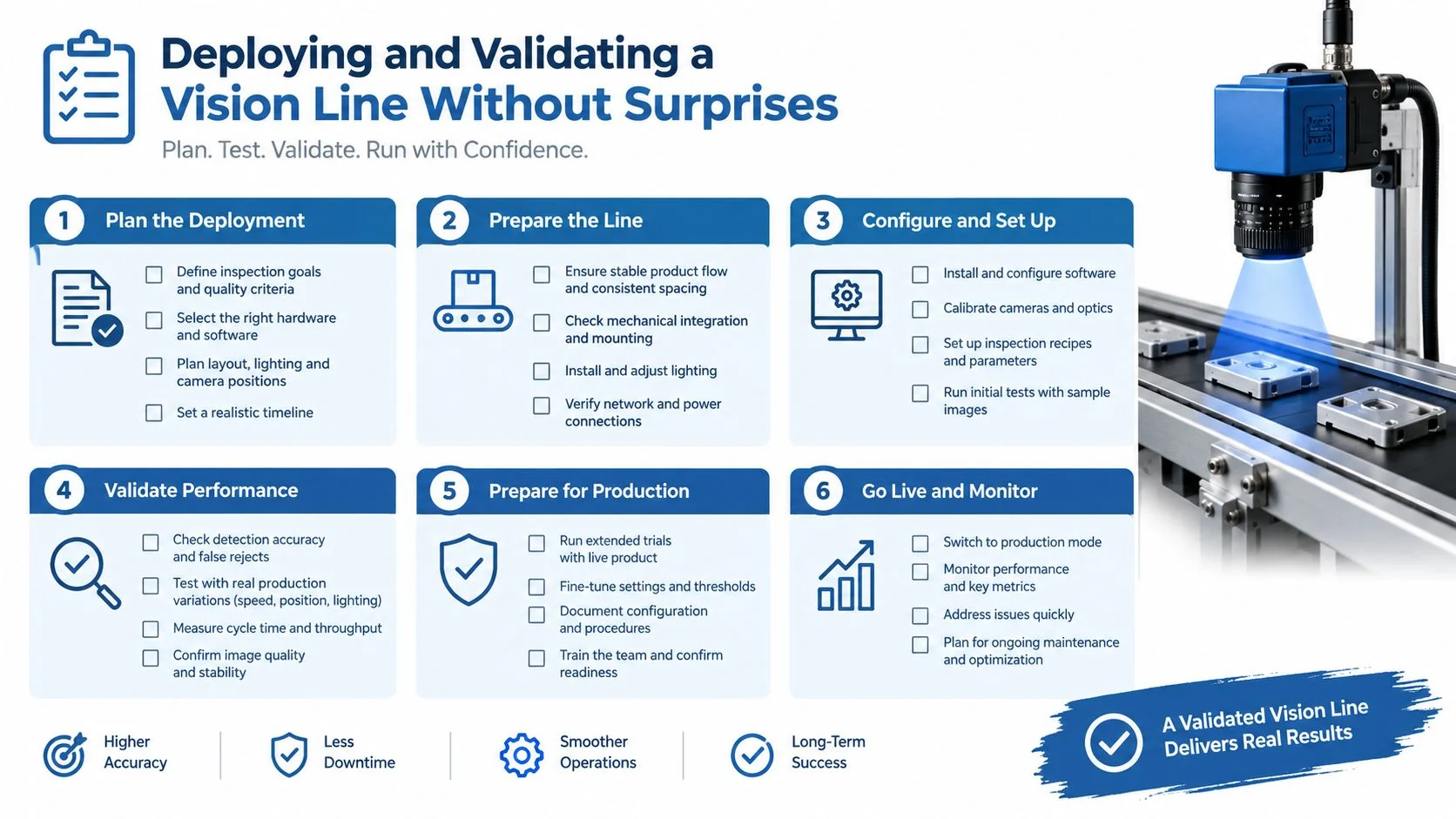
Start smaller than the business sponsor wants. A useful pilot cell covers one SKU, one shift, and one defect class. That scope keeps failures diagnosable and prevents the team from confusing changes in product geometry, operator behavior, and defect definition.
Build the image set before selecting the final model. Include approved parts, clear rejects, marginal parts, and examples from different lots, fixtures, orientations, and lighting conditions. Record the camera configuration, illumination settings, part provenance, operator judgment, and final disposition. If the image set can't explain why a part was labeled pass or fail, it won't support a trustworthy validation process.
Lock acceptance criteria early
Define the sign-off rules before the integrator starts tuning thresholds. At minimum, agree on:
- Defect escape behavior, including which defect classes are safety or regulatory critical.
- False-reject tolerance, including who investigates ambiguous results.
- Throughput loss budget, measured against the production takt rather than a laboratory trigger.
- Operator override rate, with a reason code for every override.
- Fault behavior, including what the PLC does when the camera, network, or model is unavailable.
- Data retention, covering images, decisions, model versions, and audit records.
Factory acceptance testing should happen in the integrator's lab using representative parts and the intended controls sequence. Site acceptance testing then runs on the actual line at production takt, with real fixtures, operators, lighting, and upstream variation. A parallel run gives the team an opportunity to compare automated decisions with established inspection without immediately making the camera the sole gatekeeper.
The documented AI vision proof-of-concept example for dental manufacturing is a useful reminder that a pilot can reveal a better operational design than the original automation concept. Validation isn't only about proving the model. It should also prove that the proposed workflow helps people resolve exceptions.
Protect the system after go-live
Lighting drift, fixture wear, lens contamination, and camera movement can change the image without changing the model. Put these controls into the maintenance plan:
- Lighting checks: Monitor intensity and replace or service aging illumination before it changes pass-fail behavior.
- Calibration: Define a documented recalibration trigger based on maintenance events, fixture changes, and measured drift.
- Model control: Version every model, recipe, and threshold, with approval and rollback procedures.
- Golden-image review: Recheck a fixed reference set after maintenance or software updates.
- Escalation: Identify who owns a false call, a missed defect, a PLC fault, and a hardware failure.
The line team should know whether a failure means “reject the part,” “hold the part for review,” or “continue with manual inspection.” Ambiguous fallback behavior turns a manageable technical fault into an uncontrolled quality risk.
ROI, Use Cases, and What Real Manufacturing Pilots Actually Do
The ROI case begins with a baseline, not a dashboard. Measure the recurring cost of scrap, rework, warranty exposure, inspection labor, and downtime before choosing a camera or model. Then identify which decision the vision cell will remove, accelerate, or make more consistent.
Representative applications include PCB solder inspection, robotic weld guidance, and pharmaceutical blister-pack integrity checks. Each has a different value mechanism. Solder inspection can catch process variation before boards move downstream. Weld guidance can reduce dependence on manual positioning and improve repeatability. Blister-pack inspection can verify product presence, package integrity, and printed information where a missed error carries significant quality consequences.
The economics often fail for reasons that don't appear in the initial business case. Changeovers can consume the expected labor saving. Operators may create an exception queue if the system gives them no useful explanation. A model can detect defects accurately while the line loses throughput because the reject mechanism, image transfer, or PLC handshake wasn't engineered for the actual cycle.
Measure the decision chain
| Use Case | Measured Outcome | Payback Window | Lesson Learned |
|---|---|---|---|
| PCB solder inspection | Establish defect escapes, false rejects, review workload, and downstream rework before and after deployment | Calculate from the plant's baseline, not a generic benchmark | Detection value depends on catching the defect early enough to prevent downstream cost |
| Automotive robotic weld guidance | Measure robot correction behavior, cycle-time effect, manual intervention, and repeatability | Calculate from avoided manual decisions and downtime | Guidance requires deterministic latency and reliable coordinate handoff |
| Pharma blister-pack integrity | Measure missing-product escapes, packaging rejects, manual inspection effort, and exception handling | Calculate from quality exposure and labor baseline | Inspection must include the package workflow, not only image classification |
Public application references such as this overview of AI vision use cases for factory floors can help teams build an initial shortlist, but a shortlist isn't evidence of fit. The validation sample must come from the actual process, and the outcome must be stated in plant terms.
A useful ROI test is simple: can the vision cell take a recurring decision away from a person without creating a larger review burden? If the answer is yes, the business case can be strong even when the model isn't perfect. If the system merely adds another dashboard for operators to watch, it may increase technical complexity without changing the cost structure.
For AI in manufacturing, this distinction is critical. The highest-value deployment is usually the one that connects perception to an action, such as a controlled reject, a robot correction, a process hold, or a traceable quality event. A visual prediction with no reliable operational response is only an observation.
Lessons From the Field and Where to Go Next
The practical playbook is shorter than most vendor presentations:
- Lock optics and lighting first: Don't tune an algorithm against images that will change after installation.
- Reserve project time for image curation: Golden-image work is engineering work, not administrative labeling.
- Test the handshake early: Triggering, result acknowledgment, reject timing, MES events, and fault states belong in the pilot.
- Make false calls visible: Track false rejects beside detection performance so operators and quality teams see the actual trade-off.
- Treat uptime as a quality metric: An accurate system that frequently falls back to manual inspection isn't delivering stable control.
- Plan for the second station: Reuse camera standards, lighting methods, data schemas, and support procedures where the process allows it.
The first vision station usually carries the largest integration burden because the team is establishing standards for networking, PLC behavior, image storage, model governance, maintenance, and operator response. The marginal effort for additional stations can fall when those patterns are reusable, but only if the first deployment is documented rather than treated as a one-off engineering project.
Industrial vision systems also fit into a broader AI roadmap. A plant that has learned to curate production data, validate edge inference, manage model versions, and connect decisions to controls is better prepared for predictive maintenance, process optimization, and automated root-cause analysis. The AI for Manufacturing database provides searchable records of documented industrial AI implementations with filters for industry, use case, technology, and company size, which can help engineers compare deployment patterns before committing to a vendor stack.
Bring these questions to the next vendor conversation:
- What is the smallest defect, and how many sensor pixels represent it?
- Which lighting geometry controls the surface reflections?
- What happens when the model is uncertain?
- How are false rejects reviewed and labeled?
- What is the complete trigger-to-actuator latency?
- How does the system version models, recipes, and calibration data?
- What does the PLC do during a camera, network, or compute failure?
- Which integration tasks belong to the vendor, integrator, controls team, and plant IT group?
- What evidence will determine whether the pilot proceeds, pauses, or stops?
Industrial vision systems are most valuable when they become a dependable perception layer for AI in manufacturing, linking cameras and optics to edge inference, PLC control, MES traceability, robotic guidance, and measurable quality decisions. Start with one constrained production problem, validate the complete operating workflow, and scale only after the line team trusts both the image and the action that follows it.
If you're evaluating a vision project, document one target defect, one representative image set, one production takt, and one PLC response before requesting proposals. Use those requirements to compare architectures and invite vendors to test against your real parts, then use the results to define a controlled pilot with explicit escape, false-reject, latency, and uptime criteria.
